- 您现在的位置:买卖IC网 > Sheet目录17380 > SP6127EB (Exar Corporation)EVAL BOARD FOR SP6127
______________________________________________________ GENERAL OVERVIEW
SP6127
Vout
CP1
2pF
RZ
CZ2
130pF
RZ2
200k
CZ
R1
200k, 1%
VFB
Vref =0.6V
R2
Error Amplif ier
Figure 1- RZ and CZ in conjunction with internal compensation components form a Type-
III compensation network
Loop Compensation Example 1 - A converter
utilizing a SP6127 has a 3.3 μ H inductor and a
22 μ F/5m ceramic capacitor. Determine
whether Type-III compensation is needed.
response of the circuit, seen in figure 2,
validates the above procedure.
Loop Compensation Example 2 - A converter
utilizing the SP6127 has a 3.3 μ H inductor and
From equation (2)
f ESRZERO
= 1.45MHz. From
a 220 μ F, 82m Aluminum Electrolytic
capacitor. Determine whether Type-III
equation (3) f DBPOLE = 18.4 kHz. Since the
compensation is needed.
condition specified in (1) is not met, Type-III
compensation must be used by adding
From equation (2)
f ESRZERO
= 8.8kHz. From
external components RZ and CZ. Using
equation (4) CZ is calculated to be 34pF (use
33pF). Following the guideline given in table 1,
a 2k RZ should be used.
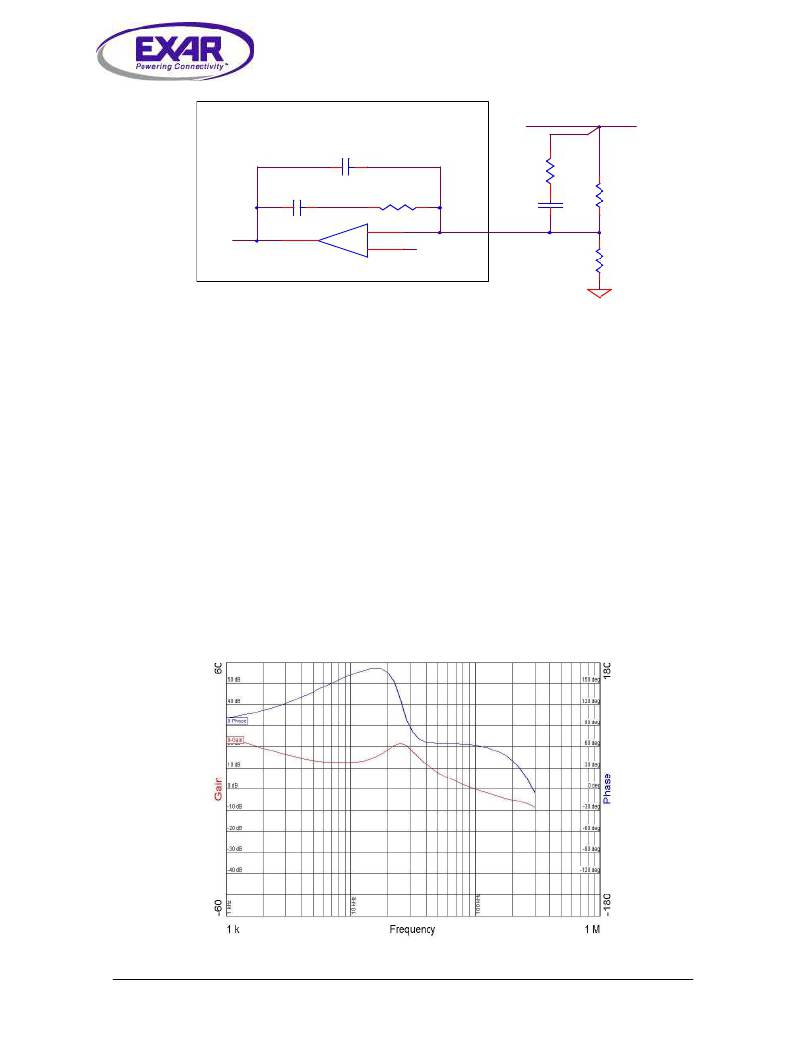
The steps followed in example 1 were used to
compensate the typical application circuit
shown on page 1. Satisfactory frequency
equation (3) f DBPOLE = 5.9kHz. Since the
condition specified in (1) is not met, Type-III
compensation needs to be used by adding
external components RZ and CZ. Using
equation (4) CZ is calculated 108pF (use 100
pF). Since f ESRZERO / f DBPOLE is approximately 2,
RZ must be set at 40k .
Figure 2- Satisfactory frequency response of typical application circuit shown on page 1.
Crossover frequency f c is 100kHz with a corresponding phase margin of 60 degrees.
Jan28-08 RevE
SP6127 TSOT-6 PFET Buck Controller
Page 5
? 2007 Exar Corporation
发布紧急采购,3分钟左右您将得到回复。
相关PDF资料
R1S8-1524/P-R
CONV DC/DC 1W 15VIN 24VOUT
R1S8-1515/P-R
CONV DC/DC 1W 15VIN 15VOUT
A9CCG-0506F
FLEX CABLE - AFG05G/AF05/AFG05G
ECM08DRTS
CONN EDGECARD 16POS DIP .156 SLD
SP6126EB
EVAL BOARD FOR SP6126
R1S8-1512/P-R
CONV DC/DC 1W 15VIN 12VOUT
SP6125EB
EVAL BOARD FOR SP6125
R1S8-1509/P-R
CONV DC/DC 1W 15VIN 09VOUT
相关代理商/技术参数
SP6127EK1
制造商:SIPEX 制造商全称:Sipex Corporation 功能描述:Evaluation Board Manual
SP6127EK1L
制造商:SIPEX 制造商全称:Sipex Corporation 功能描述:High-Voltage, Step-Down Controller in TSOT6
SP6127EK1-L
功能描述:DC/DC 开关控制器 RoHS:否 制造商:Texas Instruments 输入电压:6 V to 100 V 开关频率: 输出电压:1.215 V to 80 V 输出电流:3.5 A 输出端数量:1 最大工作温度:+ 125 C 安装风格: 封装 / 箱体:CPAK
SP6127EK1L/TR
制造商:SIPEX 制造商全称:Sipex Corporation 功能描述:High-Voltage, Step-Down Controller in TSOT6
SP6127EK1-L/TR
功能描述:电压模式 PWM 控制器 High-Voltage Step Down Controller RoHS:否 制造商:Texas Instruments 输出端数量:1 拓扑结构:Buck 输出电压:34 V 输出电流: 开关频率: 工作电源电压:4.5 V to 5.5 V 电源电流:600 uA 最大工作温度:+ 125 C 最小工作温度:- 40 C 封装 / 箱体:WSON-8 封装:Reel
SP6128A
制造商:SIPEX 制造商全称:Sipex Corporation 功能描述:Low Voltage, Synchronous Step Down PWM Controller Ideal for 2A to 10A, Small Footprint, DC-DC Power Converters
SP6128A_05
制造商:SIPEX 制造商全称:Sipex Corporation 功能描述:Low Voltage, Synchronous Step Down PWM Controller Ideal for 2A to 10A, Small Footprint, DC-DC Power Converters
SP6128AB
制造商:SIPEX 制造商全称:Sipex Corporation 功能描述:Non-Isolated DC-DC SIP Modules:3.0Vdc-5.5Vdc In, 0.9Vdc-3.3Vdc out, 10A
